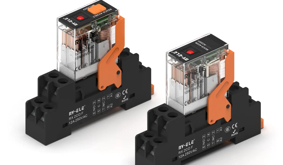

Wiring is one of the most important considerations when installing relay components in an electrical control panel. The connection method affects installation time, circuit organization, maintenance access, and the overall reliability of the control system.
A DIN Rail Relay Socket provides dedicated terminals for connecting compatible relays to external circuits. Understanding the available wiring options helps technicians select a socket that matches the application’s electrical requirements and the preferred installation method.
Screw Terminal Wiring
Screw terminals are among the most common wiring options for relay sockets. A conductor is inserted into the designated terminal and secured by tightening a screw.
This approach is popular because it is straightforward and generally allows connections to be inspected or adjusted during maintenance. The appropriate wire size and terminal tightening torque should always follow the manufacturer’s specifications.
Spring or Clamp Connections
Some relay sockets use spring-based or clamp-style terminals. These designs hold the conductor mechanically without relying on a traditional screw-tightening process.
Spring connections can simplify installation and may provide consistent contact pressure. They can be particularly useful in applications where wiring speed and resistance to vibration are important considerations.
Push-In Wiring
Push-in terminals allow compatible conductors to be inserted directly into the connection point. This can reduce installation time and create a clean wiring arrangement when the appropriate wire types are used.
Before selecting a push-in socket, check the manufacturer’s requirements for conductor size, insertion method, and whether ferrules or solid conductors are supported.
Terminal Arrangement
Beyond the connection mechanism, terminal layout is important. A socket should clearly identify coil terminals and switching contacts so that technicians can connect the circuit according to the relay’s wiring diagram.
A logical terminal arrangement can also make troubleshooting easier. When multiple relay sockets are installed in the same cabinet, consistent terminal positioning can reduce wiring confusion.
Coil Wiring
The relay coil controls the switching mechanism and must be connected to the appropriate control voltage. Depending on the relay design, the coil may operate from AC or DC power.
Always verify the relay’s rated coil voltage before making connections. Applying an incorrect voltage can prevent the relay from operating correctly or potentially damage the component.
Contact Wiring
Relay contacts may include common, normally open, and normally closed terminals. These contacts allow the relay to control another circuit according to the application’s requirements.
The correct contact terminals depend on how the control system is designed. Refer to the relay’s schematic rather than assuming that terminal positions are identical across different relay models.
Wire Size and Preparation
Choosing the appropriate conductor is essential for a reliable connection. Wire size should correspond to the expected current and the socket’s permitted terminal range.
Proper wire preparation also matters. Strip the conductor to the recommended length and ensure that no excessive bare wire remains outside the terminal. For stranded conductors, suitable ferrules may be appropriate when permitted by the terminal design.
Wiring Organization
Good wiring practices can significantly improve the usability of a control cabinet. Keep conductors routed neatly and avoid unnecessary tension on relay socket terminals.
Useful practices include:
- Labeling wires and terminals consistently
- Keeping routing paths predictable
- Avoiding excessive conductor length
- Separating circuits where appropriate
- Maintaining access to relay and terminal connections
An organized wiring layout makes future testing and maintenance more efficient.
Electrical Safety During Wiring
Power should be isolated before installing or modifying relay socket wiring. Appropriate lockout, verification, and electrical safety procedures should be followed according to the work environment.
Where a cabinet contains multiple power sources or separate control circuits, identify all relevant sources before beginning work. Never assume that switching off one circuit has de-energized the entire panel.
Choosing the Right Wiring Option
The best terminal style depends on the application. Screw terminals may be suitable where simple inspection and adjustment are priorities, while spring or push-in connections can be advantageous where faster installation or vibration resistance is important.
Manufacturers such as RY-ELE offer relay socket configurations with different terminal arrangements. Always compare the socket’s technical specifications with the relay, conductor type, current requirements, and installation environment.
Final Thoughts
Understanding relay socket wiring options makes it easier to design and maintain organized control panels. Terminal style, wiring capacity, relay configuration, conductor preparation, and circuit layout all contribute to a dependable connection.
Before installation, review the relay and socket diagrams carefully and follow the manufacturer’s wiring requirements. Selecting an appropriate connection method and maintaining good wiring practices can improve installation efficiency while making future inspection and troubleshooting much easier.